Designing a head expander can feel like a careful balancing act. It needs to be large enough to support the test article, stiff enough to maintain control, and strong enough to withstand demanding vibration environments, all while remaining light enough not to compromise shaker performance.
The good news is that established research and industry practice provide clear guidance on how to achieve this balance. This guide outlines the key considerations for designing a reliable and effective head expander in a practical, engineer friendly way.
What a Head Expander Really Does and Why it Matters
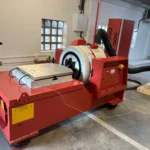
At its core, a head expander (HE) is simply the “adapter plate” between your shaker armature and whatever hardware you’re trying to test. But in practice, it’s much more than a mounting surface. The HE directly shapes:
- How evenly vibration energy is transferred to the test article
- The maximum usable frequency range of the test
- The overall stability of the shaker when supporting large or heavy payloads
Every design decision, from geometry to material selection, has a direct impact on vibration performance and test quality.
The Four Key Design Objectives
1. Minimise Mass Without Compromising Stiffness
Mass directly affects shaker performance. A heavier head expander reduces available acceleration, limits high frequency capability, and increases system loading. Lightweight materials such as magnesium alloys are often preferred due to their high stiffness to weight ratio. However, reducing mass must not come at the expense of structural rigidity. Insufficient stiffness can introduce unwanted resonances and reduce control accuracy.
2. Shift Natural Frequencies Above the Test Range
Resonances within the operating frequency range can lead to amplification, unstable control, and potential damage to both the test article and the shaker system. To avoid this, the design should aim to push natural frequencies beyond the intended test band. This is typically achieved through careful use of plate thickness, ribbing, and overall geometry. Finite Element Analysis is an essential tool for identifying and tuning these modes early in the design process.
3. Ensure Robust and Symmetrical Mounting
A head expander must offer flexible mounting options while maintaining structural integrity. Multiple bolt patterns are often required to accommodate different test setups, but these must be implemented carefully. Symmetry is critical. Reinforcement around bolt holes is necessary to prevent local weakening, which can introduce low frequency modes or uneven vibration distribution.
4. Validate Performance Through Testing
Simulation alone is not sufficient. Physical validation is essential to confirm that the head expander behaves as expected under real conditions. Modal testing, sine sweeps, and broadband excitation are commonly used to verify natural frequencies, identify unexpected resonances, and confirm uniform vibration response. Correlation between analytical models and physical measurements is a key step in ensuring design reliability.
Materials and Manufacturing Considerations
Material Selection
Magnesium alloys, such as AZ91D, are widely used due to their excellent stiffness to weight ratio, making them well suited for high frequency applications. Aluminium alloys are a practical alternative. While slightly heavier, they are easier to machine, more cost effective, and suitable for many general testing applications.
Manufacturing Approaches
Common manufacturing methods include:
- Machined plates with integrated ribs
- Cast structures followed by precision machining
Where possible, a monolithic design is preferred, as joints and interfaces can introduce unwanted dynamic behaviour.
Material removal through pocketing can be used to reduce mass, if stress levels remain within acceptable limits. All internal corners should be properly filleted to minimise stress concentrations and reduce the risk of fatigue cracking.
Optimising Geometry
Rib Design
Ribbing plays a central role in controlling stiffness and modal behaviour. Key parameters include plate thickness, rib height, rib thickness, and overall layout. Different rib configurations, such as ring structures or cross members, can be used depending on the application. Combining Finite Element Analysis with design of experiments methods allows for efficient optimisation of stiffness versus mass.
Bolt Pattern Layout
Bolt patterns should be designed with symmetry and adequate spacing in mind. Sufficient material must be maintained between holes to preserve structural integrity. Additional reinforcement may be required around complex or multi pattern layouts to prevent local compliance and ensure consistent vibration transmission.
Analysis and Testing
Virtual Validation
Before manufacturing, simulation should be used to:
- Identify natural frequencies through modal analysis
- Evaluate response under random and harmonic loading
- Optimise mass and stiffness trade-offs
This stage helps identify and resolve potential issues early in the design process.
Physical Validation
Once manufactured, the design should be verified through:
- Experimental Modal Analysis to confirm predicted modes
- Sine sweeps and broadband excitation to detect resonances
- Measurement of acceleration uniformity across the surface
These tests ensure that the head expander performs as intended under real operating conditions.
Common Pitfalls and How to Avoid Them
Resonances within the operating range
Often caused by insufficient stiffness or poor rib placement. This can be addressed by refining the geometry and increasing structural rigidity where needed.
Excessive mass
Overly heavy designs reduce shaker capability. Optimisation through material selection and geometric refinement is essential.
Non-uniform vibration response
Typically the result of asymmetry or weak regions around bolt patterns. Maintaining symmetry and reinforcing critical areas helps mitigate this issue.
Poor correlation between simulation and reality
Usually due to incorrect assumptions in the model. This can be resolved by refining boundary conditions and validating results with physical testing.
Fatigue and cracking
Sharp corners and thin sections can lead to stress concentrations. Proper filleting and spacing between features significantly improve durability.
Final Thoughts
Designing a head expander requires careful consideration of mass, stiffness, geometry, and validation. A successful design is lightweight yet rigid, well supported, and thoroughly tested. By following these best practices, engineers can develop head expanders that deliver reliable, accurate, and repeatable vibration test results while protecting both the test article and the shaker system.
References
- Bandu, Yenugula, Shirish (2021) — “Design and analysis of head expander of electrodynamic shaker for vibration testing,” AIP Conference Proceedings 2358, 050010.
- Dal & Baklacı (2019) — “Design, fabrication and vibration analysis of a lightweight head expander for a high frequency electrodynamic shaker,” Materials Testing 61(10).
- Jeong & Cho (2016) — “Optimal Design of Head Expander for a Lightweight and High Frequency Vibration Shaker.”